















What are you looking for?
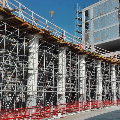
Supporting a high or heavily loaded concrete slab requires more than placing temporary supports beneath the formwork. The support layout must transfer loads efficiently, accommodate the slab geometry, provide sufficient working space, and remain practical throughout assembly, pouring, stripping, and relocation.
A shoring tower is often selected when individual props are not suitable for the required height, load, or site arrangement. However, tower quantity and spacing should never be determined from slab area alone. Contractors need to evaluate structural loads, support elevations, beam positions, foundation conditions, and the planned construction sequence before preparing the layout.
Individual slab props are practical for many conventional floors. A shoring tower becomes more suitable when the project involves:
High floor-to-floor dimensions;
Thick slabs or deep transfer beams;
Concentrated construction loads;
Bridge decks and infrastructure structures;
Large openings beneath the supported area;
Uneven or changing support elevations;
Slab tables that need to be moved as complete units.
The decision should be based on the complete temporary support requirement. A tall slab does not automatically require the heaviest available tower, while a lower structure may still need a high-capacity system because of concentrated beam or equipment loads.
Before preparing a tower layout, the project team should collect accurate structural and site information.
Essential data includes:
Slab thickness and concrete volume;
Beam dimensions and locations;
Floor-to-floor and clear support heights;
Formwork and construction live loads;
Pour sequence and concrete placement method;
Openings, ramps, steps, and level changes;
Available tower footprints;
Ground or slab-bearing conditions;
Crane and material-handling access;
Required stripping and reshoring sequence.
Plans and sections should identify areas where the support demand changes. A uniform tower grid may be inefficient when the slab contains deep beams, cantilevers, drop panels, or large openings.
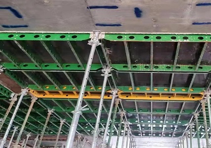
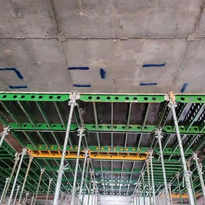
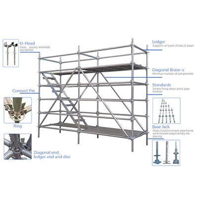
The tower does not support concrete directly. Loads normally pass through the facing material, secondary beams, primary beams, head jacks, tower frames, base jacks, and finally into the supporting surface.
Each connection affects the performance of the complete system. The project team should verify:
How the slab formwork transfers loads into the tower heads;
Whether primary beams are properly centered;
How tower legs distribute loads onto the base;
Whether the supporting slab or ground can resist those reactions;
Whether bracing controls movement in both directions.
When comparing shoring tower systems, buyers should evaluate the complete load-transfer arrangement rather than comparing frame capacity alone. Head supports, jacks, braces, beams, and foundation preparation all influence the final configuration.
Large slabs should be divided into zones according to load and geometry.
Regular slab areas may use a repeated tower grid that simplifies material planning and installation.
Deep beams, transfer slabs, or concentrated loads may require closer tower spacing, additional primary beams, or different support arrangements.
Slab edges need careful support because tower placement may be restricted. The layout must also provide room for edge formwork and working platforms.
Stairwells, service openings, ramps, and changes in level can interrupt a standard grid. These areas should be planned individually rather than adjusted informally during installation.
Dividing the project into support zones helps avoid both under-supporting critical areas and using unnecessary equipment in lower-load sections.
A tower footprint must fit beneath the slab while maintaining access for workers, reinforcement installation, concrete operations, and material movement.
Buyers should confirm:
Available frame widths and lengths;
Frame height combinations;
Base and head-jack adjustment ranges;
Bracing positions;
Access between adjacent towers;
Compatibility with slab beams or table formwork;
Whether towers can be moved by crane or trolley.
Using too many small units may increase assembly labor and create congested working areas. Oversized towers may be difficult to position around columns, walls, or openings. The best layout balances load capacity, available space, and installation efficiency.
A shoring tower can only perform correctly when its base is properly supported.
Before installation, inspect:
Concrete strength of the supporting slab;
Ground compaction and bearing capacity;
Drainage and water accumulation;
Local steps or surface irregularities;
Base plate or sole-board requirements;
Openings or services beneath tower legs;
Loads transferred to lower floors.
Where towers stand on an existing slab, the load may need to be carried through multiple floors using reshoring. The support plan should therefore consider the complete structure below, not only the active construction level.
The layout should also reflect how towers will be erected, adjusted, dismantled, and moved.
Vertically assembled towers may suit restricted areas, while horizontal ground assembly can reduce work at height when sufficient space and lifting equipment are available. Larger preassembled units may improve cycling efficiency, but they require suitable crane capacity and lifting access.
Before finalizing the layout, determine:
Where components will be stored;
Where ground assembly can take place;
How complete towers will reach the pour area;
Whether relocation routes remain open;
How towers will be released after stripping;
Which units will be reused in the next zone.
A practical movement plan can reduce downtime between concrete pours.
An effective request for quotation should include:
Structural drawings and slab sections;
Required support heights;
Preliminary load information;
Proposed pour sequence;
Available crane capacity;
Slab formwork type;
Project schedule;
Reuse requirements;
Delivery location and packing needs.
The supplier should return a component list, proposed configuration, tower dimensions, accessories, and assembly guidance. Buyers should also confirm whether stairs, platforms, movement devices, and spare parts are included or optional.
Planning a shoring tower layout requires coordination between structural requirements, formwork design, site access, foundation conditions, and construction sequencing.
The most economical solution is not necessarily the arrangement with the fewest towers or the highest individual capacity. A well-planned system uses the appropriate tower quantity, distributes loads efficiently, fits the available workspace, and supports repeatable construction cycles.
Project-specific layouts and load calculations should always be completed or approved by qualified temporary works professionals before installation.
Spacing depends on slab and beam loads, formwork beam capacity, tower capacity, support height, foundation conditions, and the approved temporary works design.
Not always. Deep beams, openings, transfer zones, edges, and level changes may require different support arrangements.
Yes, when the slab and supporting structure can resist the applied reactions. Reshoring may be required on lower floors.
Both methods may be possible. The choice depends on available space, tower height, crane access, manufacturer instructions, and the approved method statement.
Provide slab plans, sections, beam details, floor heights, openings, support conditions, and the proposed concrete-pour sequence.